Unique selling points
- No need of hydraulic pressure to perform water desalination
- Modular and compact technology
- Possibility to treat high TDS brines
- Less fouling and scaling tendency
- Working range temperature between 40ºC and 80ºC
- Low-grade heat sources, such as waste heat or solar/thermal energy
- Capability to recover volatile compounds
Description of the technology
Membrane distillation (MD) is a novel desalination technology that produces fresh water in a pure vapor state from seawater using porous membranes with hydrophobic surfaces (Ruiz-Aguirre et al., 2019).
During the MD process, seawater comes in contact with one side of the membrane, but due to the high hydrophobicity of the membrane surface, the water does not penetrate the pores of the membrane, so only water vapor passes through the membrane. This process results in a highly pure distillate solution and a concentrated feed solution where the non-volatile solutes are retained (Choi et al., 2016).
MD process is driven by the temperature difference formed between the feed at high temperature and the distillate. This creates a vapor pressure difference between feed and distillate solutions, which causes evaporation at the feed side of the membrane and condensation at the distillate side.
The MD process can be applied in four different configurations (Fig. 1). These configurations differ from each other in terms of the medium in contact with the membrane at the permeate side (Alkhudhiri et al., 2012).
- Direct Contact MD (DCMD)
In DMCD the membrane is in direct contact with both liquid phases (feed and permeate). This is the simplest configuration and is capable of producing reasonable high flux despite its high heat lost by conduction. It is best suited for applications such as desalination and the concentration of aqueous solutions.
- Air Gap MD (AGMD)
In AGMD an air gap is interposed between the membrane and the condensation surface. This configuration has the highest energy efficiency due to reduced heat lost by conduction. However, the flux obtained is generally low due to low-temperature differences across the membrane, and therefore, larger surface areas are required. The AGMD configuration can be widely employed for most MD applications, particularly where energy availability is low or in those cases where volatile compounds need to be removed from aqueous solutions.
- Sweeping Gas MD (SGMD)
In SGMD a stripping inert gas is used at the permeate side to carry the vapor to condense outside the membrane module. Similarly, to AGMD, this configuration uses a gas barrier to reduce heat loss. However, in this case, the gas is not stationary, which enhances the mass transfer coefficient. In this technique, the vapor diffuses in the stripping gas as it is swept. This results in a need for a large condenser, which represents the main disadvantage of this configuration. Furthermore, an air blower or a compressor are needed to maintain the operation of this configuration, which causes an increase in both CAPEX and OPEX. SGMD configuration is suited for solutions containing volatile compounds.
- Vacuum MD (VMD)
In VMD the permeate side is vapor or air under vacuum conditions. This configuration makes the heat lost conduction negligible and allows for condensation outside the membrane module. VMD is used to separate volatiles from an aqueous solution.
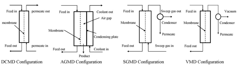
Fig. 1 Membrane distillation configurations
Flow scheme of the technology
In the framework of the ULTIMATE project, in the Work Package 1, MD is applied to treat the concentrate of the reverse osmosis (RO) process (e.g. the brine), aiming at the achieving minimum liquid discharge (MLD), thus maximizing the water recovery throughout the entire process. In this context, the AGMD configuration has been selected, since it shows the best performance in terms of energy efficiency and capability for latent heat recovery. The flow scheme of the MD pilot plant installation which will be constructed in the Tarragona demonstration site can be represented in Fig. 2.
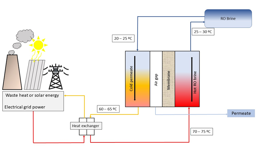
Fig. 2 Membrane distillation process layout
Synergetic effects and motivation for the implementation of the technology
- MD incorporates improving aspects compared to conventional thermal-based desalination technologies.
Due to the possibility to use low-grade thermal energy, MD can use waste heat or renewable energies to operate the system, the risk of corrosion is almost negligible, can be applied in small and decentralized treatment plants, and therefore the operating and capital costs are lower. In addition to that, in the MD process there is no need to cool down the produced water, since the latent heat of condensation is used to pre-heat the brine to be treated in the same process. Finally, conventional thermal-based technologies can achieve high quality permeate, but low-to-moderate water recovery indexes, while MD technology shows higher water recovery values without losing the high quality of the produced permeate (Curto et al., 2021).
- MD incorporates improving aspects compared to conventional membrane-based technologies
Comparing to other membrane separation processes, applying the MD allows to achieve 100% (theoretical) rejection of inorganic ions, macromolecules, and other non-volatile compounds, thus offering the possibility to produce high quality permeate (10 ppm of TDS). At the same time, MD requires lower operating pressure thank conventional pressure-driven membrane-based technologies. The latter aspect also results in less and more simple requirements on membrane mechanical properties. Due to the inner mechanisms governing the mass transfer during the MD process, it is also insensitive to feed concentration, being indeed able to treat brines up to 300,000 ppm of TDS (Al-Obaidani et al., 2008).
Technology requirements and operating conditions
The MD technology does not have significant requirements to ensure its correct operation. Since the driving force is the vapor pressure difference between the feed side (salty water or brine) and the permeate side (distillate), the temperature is the main constrain of such process. In the following Tab 1, the operating conditions are summarized.
Tab 1. Membrane distillation operation conditions.
|
Parameter |
Min |
Max |
Reference |
|
Tin |
40ºC |
90ºC |
|
|
Tout |
10ºC |
25ºC |
|
|
Dt |
30ºC |
80ºC |
|
|
|
|
|
|
|
Pretreatment |
To reduce wetting |
||
|
Flow |
Depends on the application |
||
Key performance indicators
In the following Tab 2, the most important MD key performance indicators are listed.
Tab 2. Membrane distillation Key performance indicators.
|
Indicator |
Reference value |
Unit |
Reference |
|
Flux |
4 – 6 |
LMH |
|
|
Thermal efficiency |
1 - 7 |
GOR* |
|
|
Electrical consumption |
10.3 (With waste heat) 43 (Without waste heat) |
kWh/m3 |
|
|
Permeate quality |
10 |
ppm |
|
|
Water recovery |
80 |
% |
* GOR: Gained Output Ratio = kg of distilled water produced per kg of steam consumed.
Case Studies applying the technology
Publications
- Alba Ruiz-Aguirre 1,2,*, Juan A. Andrés-Mañas 2 and Guillermo Zaragoza, Evaluation of Permeate Quality in Pilot Scale Membrane Distillation Systems, 2019
- Alkhudhiri, A., Darwish, N., and Hilal, N., Membrane distillation: A comprehensive review, 2012
- Al-Obaidani, S., Curcio, E., Macedonio, F., di Profio, G., Al-Hinai, H., and Drioli, E., Potential of membrane distillation in seawater desalination: Thermal efficiency, sensitivity study and cost estimation, 2008
- Choi, Y. J., Lee, S., Koo, J., and Kim, S. H., Evaluation of economic feasibility of reverse osmosis and membrane distillation hybrid system for desalination, 2016
- Curto, D., Franzitta, V. and Guercio, A., A Review of the Water Desalination Technologies, 2021
- G. Zaragoza 1, J. A Andrés-Mañas1 and A. Ruiz-Aguirre2, Commercial scale membrane distillation for solar desalination, 2018
- Naves Arnaldos, A., van den Broeke, J., Guleria, T., Bruni, C., Fantone, F., Touloupi, M., Iossifidis, D., Giménez Lorang, A., Sabbah, I., Farah, K., Baransi-Karkaby, K., Pidou, M., Reguer, A., Kleyböcker, A., Jährig, J., Vredenbregt, L., Thisgaard, P., D1.9 Start-up and intermediate results of plant operation from all case studies, 2023
- Ruiz-Aguirre, A., Andrés-Mañas, J. A. and Zaragoza, G., Evaluation of Permeate Quality in Pilot Scale Membrane Distillation Systems, 2019
- Sulaiman Al-Obaidania,b,∗, Efrem Curcio b,c, Francesca Macedoniob, Gianluca Di Profiob, Hilal Al-Hinaid, Enrico Drioli b,c, Potential of membrane distillation in seawater desalination: Thermal efficiency, sensitivity study and cost estimation, 2008
- Yong-Jun Choia , Sangho Leea, *, Jaewuk Koob , Seung-Hyun Kimc, Evaluation of economic feasibility of reverse osmosis and membrane distillation hybrid system for desalination, 2016
- Zaragoza, G., Andres-Mans, J. A, and Ruiz-Aguirre, A., Commercial scale membrane distillation for solar desalination, 2018