Unique selling points
- Reduction of energy consumption
- Reduction of demand for chemicals
- Optional: Avoidance of exceeding discharge limits during heavy rain events
Description of the technology
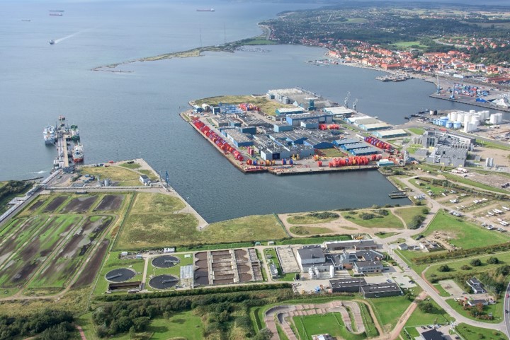
If two wastewater treatment plants (WWTPs) are neighboured, but controlled separately, a joint control system can enhance their performance and lower their environmental impact. Usually neighboured WWTPs are operated by different companies. This is also the case in Kalundborg (DK), where the effluent of an industrial WWTP is discharged to a municipal WWTP. Both WWTPs are operated separately and owned by different companies. The goal of the project ULTIMATE is to implement, operate and evaluate a joint control system for both plants.
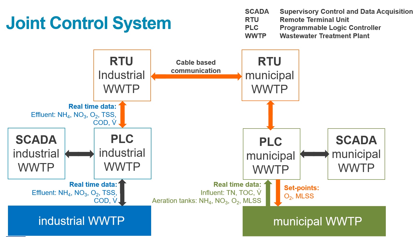
The joint control system connects two separate control systems as shown in Fig. 1. The industrial WWTP has its own control system consisting of a programmable logic controller (PLC) and a supervisory control and data acquisition (SCADA) system. The PLC uses real time data measured in the WWTP and controls the wastewater treatment process. The SCADA system displays and stores those data in a database. A remote terminal unit (RTU) of the industrial WWTP is used to send data to the RTU of the municipal WWTP. The municipal RTU receives those data and transfers them to the municipal PLC. Here, the industrial real-time data are used together with the real-time data from the municipal WWTP to control the set-points for the oxygen concentration in the aerated tanks and the mixed liquor suspended solids content in those tanks. Both parameters are crucial for a successful and energy efficient wastewater treatment process.
As shown in Fig. 1, the communication can also be redirected from the municipal WWTP to the industrial WWTP to send information about the phosphorus removal capacity in the municipal WWTP to control the precipitant dosage in the industrial WWTP. The aim is to decrease the chemical dosing rates for phosphate precipitation in the industrial WWTP and consequently, to decrease its CO2e footprint. In the near future, a buffer tank will serve as a hydraulic buffer to prevent direct wastewater discharges to the receiving water body during heavy rain events. Dependent on real time flow rate of the incoming municipal and industrial wastewater streams the storage of the municipal wastewater will be activated, when their sum exceeds a certain threshold. As soon as the sum of the flow rates decreases below this threshold, the joint control system starts the release of the stored wastewater to the municipal WWTP. In ULTIMATE, the buffer effect will be modelled only. However, its integration into the joint control system is foreseen beyond the project lifetime.
Synergetic effects and motivation for the implementation of the technology
- Reduction of energy consumption
The joint control system allows for a synergetic wastewater treatment management of both WWTPs. Especially energy can be saved due to a new predictive controlled nitrogen elimination and thus, the avoidance of over-aeration. Using an advanced control strategy, Bertanza et al. (2021) showed for their WWTP located in Italy, a reduction of 25% of the power requirement for aeration in a nitrification reactor by implementing a fuzzy control system.
- Reduction of demand for chemicals
The joint control system allows the upstream industrial WWTP to discharge its treated wastewater with a higher phosphorus load, in the case, the phosphorus removal capacity of the municipal wastewater treatment plant is sufficient for that load. The enhanced biological phosphorus removal process in the municipal wastewater treatment plant might contribute hereby to save chemicals. However, in Kalundborg, the industrial wastewater contains high calcium loads, which seem to contribute mainly to the phosphorus removal process in the municipal WWTP and decrease the demand for additional chemical dosing.
- Avoidance of exceeding wastewater discharge limits
Within ULTIMATE, the avoidance of exceeding the wastewater discharge limits is included in the modelling of the WWTPs and is foreseen to be implemented in the joint control system after the lifetime of ULTIMATE. In the near future, a hydraulic buffer shall enable the joint control system to avoid the exceedance of the discharge limits to the receiving water bodies. When the total flowrate exceeds the capacity of the municipal WWTP e.g. during heavy rain events, the buffer tank (5000 m³) of the municipal WWTP will be filled. When the flowrates of the incoming wastewaters from the industrial WWTP and the municipality decrease, the buffered municipal wastewater will be released to municipal WWTP correspondingly. Hereby, the aim is to avoid or reduce direct discharges to the receiving water body.
Technology requirements and operating conditions
A control system can only be as reliable as the real time input data are. Therefore, reliable sensors and strategies are needed to control and maintain them. For example, Fragkoulis et al. 2011 and Gerneay et al. 2020 show different approaches and models to evaluate the monitoring performance of a WWTP and detect faults in sensors and actuators. In the case of the two WWTPs in Kalundborg, the following parameters are measured as shown in Fig. 1:
- Flowrates (municipal influent and industrial effluent, both entering the municipal WWTP)
- In aeration tanks of iWWTP: ammonium (NH4), nitrate (NO3), oxygen (O2), mixed liquor suspended solids (MLSS)
- Industrial effluent: total suspended solids (TSS), total organic carbon (TOC), total nitrogen (TN), total phosphorus (TP), phosphate (PO4)
- Municipal influent: TOC, TN, and TP
- In aeration tanks of mWWTP: NH4, NO3, O2, MLSS, PO4
Key performance indicators
Depending on the situation before the implementation of the joint control system, the reachable values for the listed KPIs in Tab. 1 might vary. In the case of Kalundborg, Tab. 1 will present the results as soon as they will have been obtained and evaluated in 2024.
Tab. 1 Key performance indicators compared to the situation without joint control system; N/E = eliminated nitrogen compounds/energy required
|
Parameter |
Unit |
Min |
Max |
References |
|
Reduction in specific energy demand, expected |
% |
0 |
25 |
D1.4 ULTIMATE (in prep., expected to be published in 2024) |
|
Reduction in precipitants dosing for chemical phosphorus removal, expected |
% |
20 |
40 |
|
|
Exceedance of discharge permit, expected |
% |
0 |
||
|
Increase in N/E |
% |
tbd |
tbd |
|
Besides the reduction of both, the specific energy demand and the dosing of precipitants, the exceedance of the discharge limits to the recipient shall be avoided and is therefore an important key performance indicator. Again, this latter option is currently only modelled and will be implemented beyond the project lifetime of ULTIMATE.
As an indicator for the global performance of WWTP, the N/E index is used being the ratio between the eliminated nitrogen compounds and the energy required to achieve it (Revollar et al. 2020).
Links to related topics and similar reference projects
|
Process/technologies |
Reference |
|
Joint control system in Kalundborg |
Case Study applying the technology
Publications
- Bertanza, G., Baroni, P., Garzetti, S., Martinelli, F., Reducing energy demand by the combined application of advanced control strategies in a full scale WWTP, 2021
- Fragkoulis, D., Roux, G., Dahhou, B., Detection, isolation and identification of multiple actuator and sensor faults in nonlinear dynamic systems: application to a wastewater treatment process, 2011
- Gerneay, K., Jeppssson, U., Vanrolleghem, P., Copp, J., Benchmarking of control strategies for wastewater treatment plants, 2020
- Revollar, S., Vilanova, R., Vega, P., Francisco, M., Meneses, M., Wastewater Treatment Plant Operation: Simple Control Schemes with a Holistic Perspective, 2020