
Unique selling points
- Energy production: electricity with heat as by-product
- High electrical conversion efficiency (60 %)
- Low environmental impact due to biogas valorisation
Description of the technology
The solid oxide fuel cell (SOFC; TRL: 9) uses chemical energy bound in gases such as hydrogen, carbon monoxide or upgraded biogas to produce electricity via electrochemical reactions, supplying also heat as by-product. Hence, it can be applied wherever biogas is produced, e.g. at municipal wastewater treatment plants (WWTP) with anaerobic sludge treatment, at industrial WWTPs with anaerobic pre-treatment or at agricultural or waste-based biogas plants. In the case biogas is used, methane (CH4) must be converted first into hydrogen (H2) and carbon monoxide (CO) in the reforming process. This can be done in two ways, internally using the SOFC and/or externally via a pre-reformer. More details regarding the reforming processes can be found in Saadabadi et al. 2019. After the reforming process, H2 and CO are oxidized using oxygen ions in the SOFC in order to produce electricity.
Therefore, the SOFC consists of an anode, a cathode and an electrolyte and they are stacked layer-wise. At high temperatures, oxygen is reduced to oxygen ions at the cathode. The electrolyte transports the oxygen ions to the anode. At the anode, the fuel gases such as H2 or CO are oxidized using the oxygen ion. The operating temperature is usually between 500-1200 °C, so that high temperature heat is available as a by-product. Its electrical conversion efficiency is between 50% and 60% (Hussain and Yangping 2020, Saadabadi et al. 2019), which is higher than other electricity producing processes (e.g. combined heat and power plant) ranging between 30% and 40% (Saadabadi et al. 2019).
Using biogas as an alternative SOFC fuel to H2 or CO was proven to be viable (Saadabadi et al. 2019). However, raw biogas needs to be cleaned prior to the valorisation in a SOFC incl. the reforming process, since it usually contains traces of hydrogen sulphide (H2S), siloxanes, volatile organic compounds (VOC) and vapour condensates which can harm the SOFC. H2S and siloxanes can cause erosion and degradation of the SOFC already at very low concentrations.
In Ultimate, a domestic-scale SOFC is used at the municipal WWTP valorising the cleaned biogas from the sludge treatment facility (CS Lleida). There, Aqualia uses the BlueGEN system, developed by SOLIDpower SA (Solydera, since 03.10.22 (Solydera, 2022). BlueGEN is a commercial micro-CHP system targeted to small businesses, private households, and office buildings. Natural gas or biomethane can be used as the source of energy. With a gas input of 2.5 kW, the electrical power is up to 1.5 kW and the useable heat is 0.54 kW. Hence, it can yearly deliver electricity and heat of 13 MWhel and 7.4 MWhth, respectively (Bluegen 2023). The system is comprehensively described in Ferreira et al. 2019. To the author’s knowledge, it will be the first SOFC operated with WWTP biogas at least in Spain.
Flow scheme of the technology
Fig. 1 shows the flow scheme of the SOFC demo plant in Lleida. The SOFC is marked with number 1. The other elements serve to clean the WWTP biogas before it is sent to the SOFC. Further details about the requirements and pre-treatment of the gas are provided in the section “Requirements of the technology and operating conditions”.
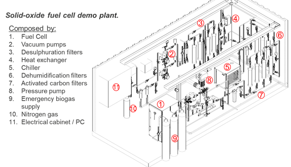
Fig. 1 Solid oxide fuel cell demo plant in the frame of Ultimate
The SOFC (BlueGEN system) comprises a pre-reformer, the SOFC stack, an afterburner and several heat exchangers (Ferreira et al. 2019). In the pre-reformer, the CH4 reacts with the steam forming H2 and CO. Simultaneously the CO reacts with the steam and forms CO2 and H2. The resulting gas is called syngas. The exhaust CH4 is then converted in the internal reformer in the SOFC stack. The endothermic methane steam reforming reaction rate leads to a significant local temperature drop near the anode inlet and hence to a temperature gradient inside the SOFC. This is unfavourable, because the key components of the SOFC are temperature-dependent (Cai et al. 2022).
The SOFC stack contains 70 planar anode-supported cells with an active area of 80 cm2. The cells are pressed and located between gas-diffusion layers and metallic interconnector plates. The anodes consist of standard nickel/yttrium-stabilized-zirconia (Ni-YSZ) cermet. A dense YSZ and a CGO (ceria-gadolinia) barrier layer serves as the electrolyte. The cathodes consist of screen-printed (La, Sr)(Co, Fe)O3, which allow operating at temperatures between 650 °C and 850 °C.
The afterburner combusts the exhaust fuel (H2, CO) and converts it into CO2 and H2O. The stream leaving the afterburner is reused to heat up the air and syngas streams.
Synergetic effects and motivation for the implementation of the technology
- SOFC: high electrical efficiency in energy production
As already outlined, the electrical conversion efficiency of a SOFC is quite high and ranges between 50% and 60% (Hussain and Yangping 2020, Saadabadi et al. 2019). Compared to other electricity producing processes (e.g. combined heat and power plant), the electrical conversion efficiency is higher, ranging between 50% and 60% compared to 30% and 40% (Saadabadi et al. 2019). The excess heat can be used for external heating systems. According to Ferreira et al. 2019, the SOFC has a combined efficiency of 82%, with 60% electrical and 22% heat efficiency.
- Low environmental impact due to lower GHG emissions
Using biogas, the technology has a low environmental impact due to the emission of green CO2. The cleaning processes of the biogas upstream to the SOFC remove, for example, hydrogen sulphide (H2S), avoiding the formation of SO2 and SOx. The electrochemical process in the SOFC, including the after-combustion process, reduces emissions of CO to a negligible range.
Technology requirements and operating conditions
In order to protect the SOFC from erosion and degradation, different requirements must be fulfilled. Biogas usually contains H2S, siloxanes, volatile organic compounds (VOC) and vapour condensates, which can harm the SOFC. Therefore, those substances must be removed. This can be done via a conventional filter for H2S, an activated carbon filter for siloxanes and VOC and for removing the humidity via cooling to 5°C and filtering through a zeolite filter as shown by Giménez-Lorang et al. 2023 (Tab. 1). Here, it should be noted that the presented values for the gas components in Tab.1 are suggestions from Aqualia and not an official requirement from the SOFC supplier. Also for the humidity, there is no requirement from the supplier’s side. However, in order to avoid condensation Aqualia suggests removing the condensate from the biogas prior to the SOFC via a condensate trap operated at a temperature below 5 °C.
Tab. 1 Typical ranges for crucial parameters (LOQ – limit of quantification)
|
Parameter |
Units |
Min |
Max |
Reference |
|
H2S |
mg/Nm3 |
<20 |
||
|
Siloxanes |
mg Si/Nm³ |
<0,05= LOQ |
||
|
VOC |
mg/Nm3 |
<0,02= LOQ |
||
|
Pressure |
mbar |
15 |
25 |
SOLIDpower 2019 |
|
Temperature (dew point) for condensate trap |
°C |
<5 |
||
|
Temperature in the SOFC |
°C |
ca. 750 |
SOLIDpower 2019 |
|
Furthermore, the SOFC should be operated continuously due to the very high operating temperatures (Tab. 1). Compared to a CHP, which can be operated at various levels with reasonable efficiency, this is a disadvantage. The continuous operation of the SOFC can be maintained via an uninterruptible power supply and a biogas buffer in the case of undesired interruptions in biogas production. Due to the operation of the SOFC with biogas containing methane, extra attention should be paid to the rules for operating technologies in an explosive atmosphere.
Key performance indicators
The electrical conversion efficiency of a SOFC is quite high and ranges between 50% and 60% (Tab. 2). Hereby, the performance of a SOFC highly depends on the purity of the fuel gas. When using conventional nickel-based anodes, H2S poisons the anode by converting Ni into Ni-sulfides (Saadabadi et al. 2019). Those attach on the anode and reduce its performance.
Tab. 2 Key performance indicators for biogas fuelled SOFCs
|
Parameter |
Unit |
min-max |
References |
|
Electrical conversion efficiency |
% |
50 – 60 |
Hussain and Yangping 2020, Saadabadi et al. 2019; Ferreira et al. 2019 |
|
Energy recovery potential for usable heat |
% |
22-25 |
Ferreira et al. 2019, Bosch 2023 |
|
Power density |
mW/cm² |
245-1400 |
Either H2S is removed upstream to the SOFC or anodes with a high resistance against H2S are used. In the latter case, the advantage is that the removal of H2S from the biogas as an additional treatment step would not be necessary anymore. Sulfur tolerant anodes are based on nickel-free electrodes such as perovskites. Saadabadi et al. 2019 and Hussain and Yangping 2020 provide a detailed overview on the recent developments of sulfur tolerant anodes. Aguilar et al. (2004) tested for example a strontium doped lanthanum vanadate anode, which could be successfully operated with H2S contents below 5%.
The achievable power density depends on the electrode materials, the type of electrolyte and the operating temperature. 1200 mW/cm² were for example achieved with a SCO/CFSCO anode and LSGM as electrolyte at a temperature of 800 °C (Zhu and Lu, 2008).
Case Study applying the technology
Publications
- Aguilar, L., Zha, S., Cheng, Z., Winnick, J., Liu, M., A solid oxide fuel cell operating on hydrogen sulfide and sulfur containing fuels, 2004
- Bluegen, https://bluegen.eu/en/, 2023
- Bosch, Energieeffizient. Dezentral. H2-ready. Mit Brennstoffzellensystemen von Bosch, 2023
- Cai, W., Zheng, Q., Yu, W., Yin, Z., Yuan, J., Zhang, Z., Pei, Y., Effects of methane pre.reforming percentage and flow arrangement on the distribution of temperature and thermal stress in solid oxide fuel cell, 2022
- Ferreira, T., Wuillemin, Z., Faulwasser, T., Salzmann, C., Van Herle, J., Bonvin, D., Enforcing optimal operation in solid-oxide fuel-cell systems, 2019
- Giménez Lorang et al., in Naves Arnaldos et al. 2023, 2023
- Hussain, S., Yangping, L., Review of solid oxide fuel cell materials: cathode, anode and electrolyte, 2020
- Larminie, J., Dicks, A., McDonald, M., Fuel Cell Systems Explained, 2003
- Naves Arnaldos, A., van den Broeke, J., Guleria, T., Bruni, C., Fantone, F., Touloupi, M., Iossifidis, D., Giménez Lorang, A., Sabbah, I., Farah, K., Baransi-Karkaby, K., Pidou, M., Reguer, A., Kleyböcker, A., Jährig, J., Vredenbregt, L., Thisgaard, P., D1.9 Start-up and intermediate results of plant operation from all case studies, 2023
- Saadabadi, S., Thattai, A., Fan, L., Lindeboom, R., Spanjers, H., Aravind, P., Solid oxide fuel cells fueled with biogas: potential and constraints, 2019
- Solydera, https://solydera.com/en/solidpower-solydera-press-release/, 2022
- Zhu, Z., Lu, Z., A Co-Fe alloy as alternative anode for solid oxide fuel cell, 2008