Unique selling points
- Protection of RO from organic and /or colloid fouling
- Reduction in the number of clean in place or membrane replacements of RO
- Reduction of the operating costs
Description of the technology
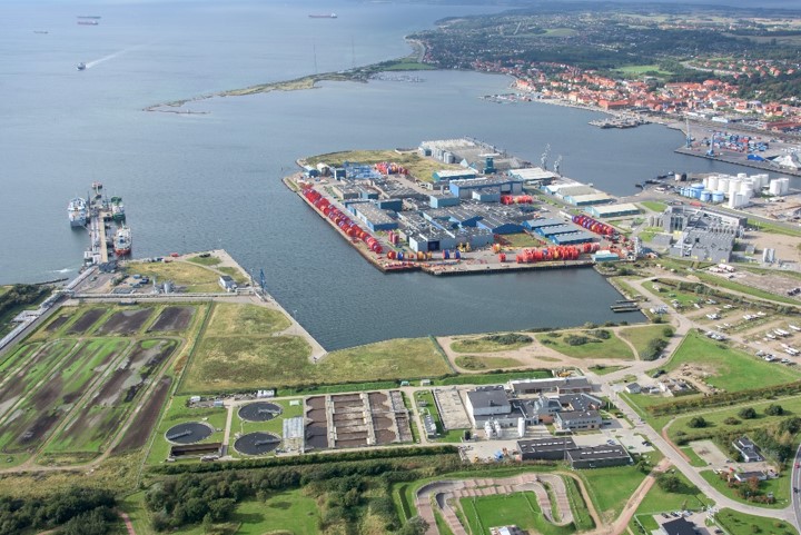
Ultrafiltration (UF) and nanofiltration (NF) membranes in combination with reverse osmosis (RO) membranes can be applied as a post-treatment of wastewater to produce fit-for-purpose water. It can be used to treat different water qualities such as pre-treated industrial wastewater from breweries as in the Lleida case study in Ultimate (Fig. 1) and secondary effluent of a municipal WWTP (treating a mix of industrial and municipal wastewater) as in the Kalundborg case study (Fig. 2).
To improve the pre-treatment process, new ultrafiltration and nanofiltration membranes with different MWCO were developed for pilot testing.
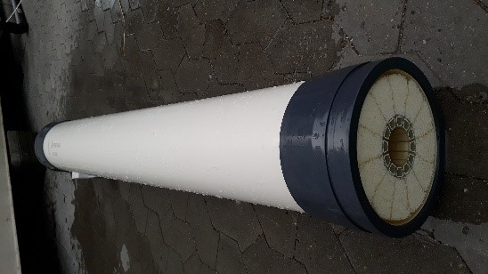
The novel ultra-tight UF membrane was developed using the Layer-by-Layer (LbL) technology and consists of hollow fibres with a diameter of 0.8 mm and filtrates from inside out. The materials of the fibres are polyvinylpyrrolidone and polyethersulfone (Pentair 2022a). A module has a diameter of 0.2 m and is 1.5 m long, with 12.000 membrane fibres and a membrane area of 40 m² (see Fig. 3). The novel ultra-tight UF membrane has a much smaller separation cut off of around 4 kDa compared to a conventional UF with a molecular weight cut off between 10 kDa and 150 kDa (Jerman et al. 2009) and a wider MWCO than an open nanofiltration membrane with 1 kDa.
It is assumed to be very well suited to protect a downstream reverse osmosis membrane from organic and/or colloid fouling. The better protection of the RO from fouling targets significant savings of cleaning chemicals for RO or membrane replacements that would be otherwise necessary by using a conventional UF instead (Jährig et al. 2023).
Due to the small molecular weight cut off and depending on the composition of the wastewater, coagulant dosing upstream of the novel membrane might be reduced or in some cases might not even be necessary in comparison to the conventional membranes.
Flow scheme of the technology
In the case study Lleida, brewery wastewater is treated via a conventional activated sludge process. The effluent shall be further treated in order to produce fit-for purpose water to be reused in cooling towers or as process water. In this case study, the combination of a NF with a MWCO of 0.8 kDa is used as pre-treatment for the RO (Fig. 1).
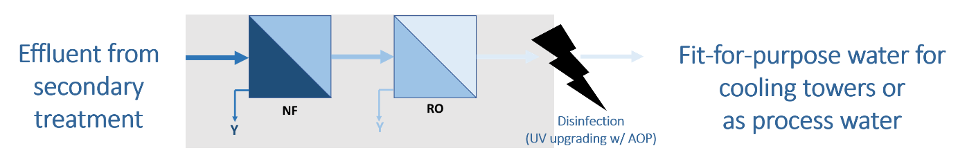
Fig. 1 Flow scheme of CS Lleida: treating effluent from the wastewater treatment plant of the brewery: NF membrane with MWCO of 0.8 kDa
In the case study in Kalundborg, the treated wastewater still contains a high fraction of non-degradable organic matter (COD > 60 mg/L) originating from the biotech wastewater. Two pilot plants are operated in parallel to assess the performance of UF and NF membranes as pre-treatment for the RO as shown in Fig. 2. The following membranes will be tested: a novel ultra-tight UF (MWOC of 4 kDa), a conventional UF (MWCO of 150 kDa) and an open NF (MWOC of 1 kDa).
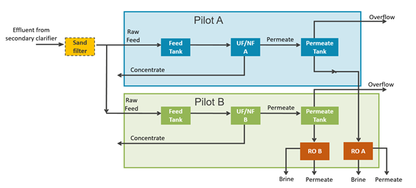
Fig. 2 Flow scheme of CS Kalundborg: treating effluent from the municipal wastewater treatment plant containing pre-treated industrial wastewater resulting from the biotech industry
Fig. 3 shows the profile of the fibre of a novel ultra-tight UF membrane and of the UF module. Fig. 4 displays the novel ultra-tight UF module and the downstream RO units of the pilot plant in Kalundborg.
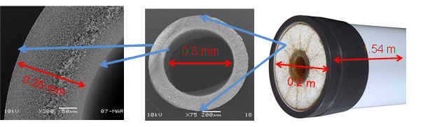
Fig. 3 UF/NF membrane with microscopic details and dimensions of membrane fibres; left: fibre wall; middle: fibre; right: module head
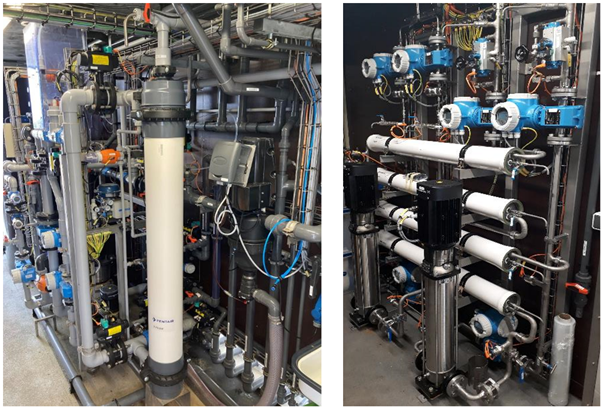
Fig. 4 Pilot plant in Kalundborg (from left to right): UF module, RO units
Synergetic effects and motivation for the implementation of the technology
- Protection of RO from organic and /or colloid fouling
Due to the much smaller molecular weight cut-off of the ultra-tight UF or open NF membranes compared to a conventional UF, colloids and large organic molecules such as biopolymers can be better retained from the RO than by a conventional UF and thus, the risk of fouling is reduced.
- Reduction in the number of clean in place or membrane replacements of RO
The retention of smaller particles and compounds that would otherwise lead to fouling on the RO membrane reduces the frequency of cleaning in place (CIP) procedures, the replacement of membranes and hence, reduce the demand for chemicals.
- Reduction of the operating costs
During first test period of the Ultimate project it was shown, that the ultra-tight UF could be operated without coagulant. In the next test period of the Ultimate project, the impact of ultra-tight UF/ open NF on RO operation will be investigated including a cross-evaluation of potential savings regarding chemical cleanings and exchange of membranes, obtaining higher flux and recovery rates as well as less flushing cycles, etc. on the RO side against additional operational efforts and costs on the UF/NF side.
Technology requirements and operating conditions
Tab. 1 shows the feed water conditions for the application of this type of membrane. In the case the chemical composition of the wastewater does not comply with the indicated ranges, a pre-treatment prior to the inflow to the ultra-tight ultrafiltration unit is recommended. Typical design parameters and measured values are shown in Tab. 2.
Tab. 1 Typical feed water conditions to apply the novel ultra-tight UF membrane*
|
Parameter |
Units |
Feed water requirements |
|
Temperature |
°C |
0 – 40 |
|
pH |
- |
2 – 11 |
|
Particle size |
µm |
< 300 |
|
Total suspended solids |
mg/L |
< 200 |
|
Ozone |
mg/L |
0 |
|
Free chlorine |
mg/L |
< 500 |
* Similar to X-Flow HFW1000 [Pentair 2022b]
Tab. 2 Typical ranges for operating parameters of the novel ultra-tight UF membrane
|
Parameter |
Unit |
Design by Pentair |
Measured during pilot time |
|
Operation |
|
crossflow with bleed |
crossflow with bleed |
|
MWCO |
kDa |
4 |
|
|
Permeability |
L/(m²*h*bar) |
40-80 |
|
|
Flux |
L/(m²*h) |
20-40 |
25 –32.5 |
|
Recovery |
% |
60-80 |
80 |
|
Cross flow velocity |
m/s |
|
0.3 – 0.5 |
|
System pressure |
bar |
max. 6 |
|
|
TMP |
bar |
0.2 – 1 (max. 6) |
0.25 – 2.0* |
|
Chlorine resistance |
ppm hour |
100 000 |
|
|
Specific energy consumption |
kWh/(m³ WW) |
0.1 – 0.3** |
|
* depending on feed water quality
** Estimation by Pentair
Key performance indicators
Depending on the source of the wastewater the key performance indicators can vary as shown on Tab. 3.
Tab. 3 Key performance indicators for the novel ultra-tight UF membrane
|
Parameter |
Unit |
Value |
References |
|
Turbidity Permeate |
NTU |
< 0.2 |
Estimated based on X-Flow XF64 Membrane [Pentair 2022a] |
|
Total suspended solids Permeate |
mg/L |
< 0.2 |
Estimated based on X-Flow XF64 Membrane [Pentair 2022a] |
|
Bacteria (E. coli) |
Log removal |
> 4 – 6 |
Estimated based on X-Flow XF64 Membrane [Pentair 2022a] |
|
Viruses (som. Coliphage) |
Log removal |
>2 – 4 |
|
|
Parasites (C. Perfringens) |
Log removal |
>4 – 6 |
|
|
Intervals backwash of UF |
min |
30 – 60 |
|
|
Intervals of CEB/CEC of UF |
h |
24 |
|
|
Intervals of CIP of UF |
months |
3 – 12 |
|
|
Intervals CIP of subsequent RO |
weeks |
1 – 2 |
CEB – chemical enhanced backwash
CEC – chemical enhanced cleaning
CIP – cleaning in place
Case Studies applying the technology


Publications
- Jährig, J., Vredenbregt, L., Thisgaard, P., Kleyböcker, A., CS9 Kalundborg (Denmark), 2023
- Jerman, D. Pronk, W., Boller, M., Schäfer A., The role of NOM fouling on the retention of estradiol and ibuprofen during ultrafiltration, 2009
- Naves Arnaldos, A., van den Broeke, J., Guleria, T., Bruni, C., Fantone, F., Touloupi, M., Iossifidis, D., Giménez Lorang, A., Sabbah, I., Farah, K., Baransi-Karkaby, K., Pidou, M., Reguer, A., Kleyböcker, A., Jährig, J., Vredenbregt, L., Thisgaard, P., D1.9 Start-up and intermediate results of plant operation from all case studies, 2023
- Pentair, X-Flow XF64 Membrane, 2022
- Pentair, X-Flow HFW1000 Membrane, 2022