Unique selling points
- Removal of most dissolved pollutants from water including salts, bacteria, viruses and micro-pollutants
- Production of high quality water for reuse applications including indirect potable uses
- Compact and easily automated technology. Standarized system easy to scale
Description of the technology
Naturally, if two solutions with respectively high and low salinities are separated by a semi-permeable membrane, the water will diffuse through the membrane from the low salinity side to the high salinity side to reach an equilibrium in concentration on both sides (Fig. 1a). This is known as osmosis. Alternatively, if a pressure, greater than the natural osmotic pressure, is applied on the high salinity side, the water will diffuse through the membrane to the low salinity side producing a large volume of clean water (permeate) and a small volume of concentrate (brine) (Fig. 1b). This is the basis for reverse osmosis (RO) membranes. Due to their ability to remove salts from water RO membranes have largely been applied for sea water desalination but they are also applied for the purification of treated effluents for water reuse, generally where high quality is required such as potable uses. Indeed, RO membranes are capable of achieving complete removal of other contaminants from water such as viruses, ions and organic micro-pollutants (Fig. 2). Commonly, RO membranes are thin film composite (TFC) membranes with a polyamide active layer and structured in spiral wound elements in which membrane sheets are glued together and rolled around a central permeate collection tube (Fig. 3). It should be noted that other materials (e.g. cellulose acetate) and configurations (e.g. hollow fibre) are also commercially available.
|
|
|
|
(a) |
(b) |
|
Fig. 1 Principles of (a) osmosis and (b) reverse osmosis. |
|
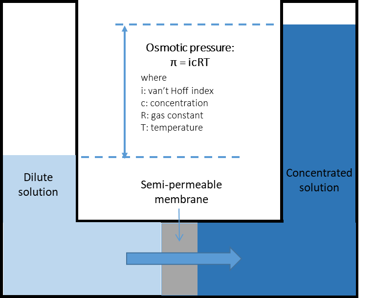
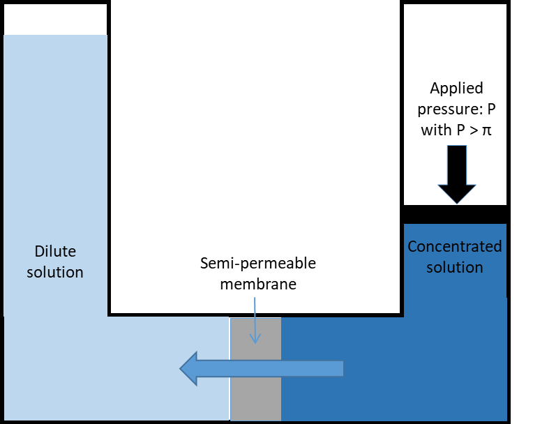
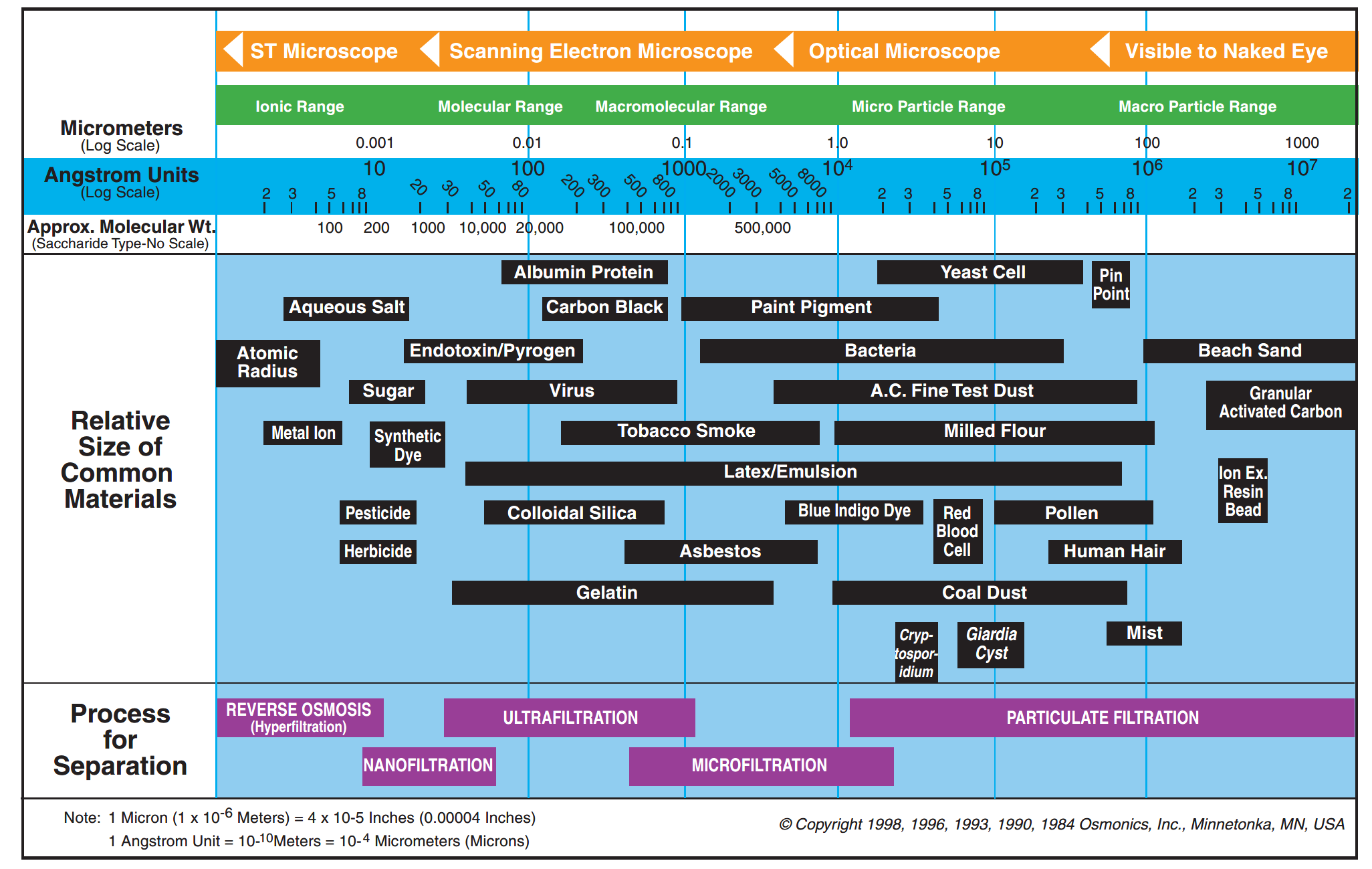
Fig. 2 Filtration range for different membrane types (Radcliffe and Zarnadze, 2004).
|
|
|
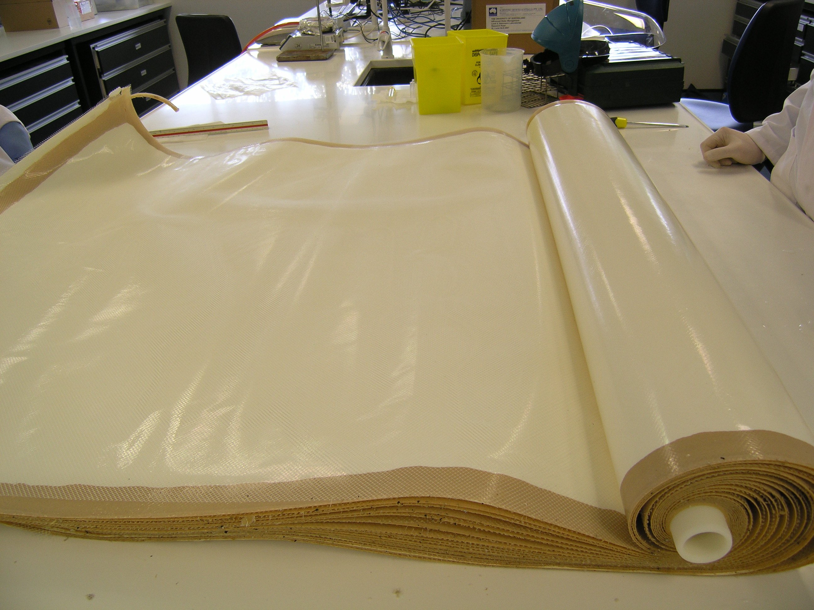

Fig. 3 Spiral wound RO membrane element.
Flow scheme of the technology
RO membrane elements (Fig. 3 and 4a) are grouped and placed in modules, also called pressure vessels (Fig. 4b) for their operation at the required pressure. In each pressure vessel, the elements (typically 3 to 8) are connected in series. The feed water to be treated will enter the first element, flow through the length of the element and then into the next element until the end of the module. As some of the water permeates through the membrane, solute concentration increases along the length of each element and module. The passage of water and other compounds through the membrane occurs by diffusion which is directly impacted by the bulk concentration and then means that poorer permeate quality is produce along the length of the membranes. The overall permeate quality is then established from the blend of permeates from all elements. Also, as the feed concentration increases, the osmotic pressure increases and filtration performance decreases as higher pressure is required to obtain similar permeabilities. A staging system (different passes or stages) can then be implemented to improve the permeate quality or the recovery rate (i.e. fraction of feed water converted to permeate).
In order to improve permeate quality often for concentrated streams (e.g. sea water desalination), a two pass system can be used in which the permeate produced from the first stage is fed into a second stage for polishing (Figure 5a). Typical recovery for two pass systems with seawater is around 50%. For improved recovery (e.g wastewater treatment), 2 or 3-stage systems are used where the pressure vessels from each stage are connected through the concentrate (Figure 5b) that is feed to the next stage. In this case, typical recoveries are around 75 to 85%.
|
|
|
|
(a) |
(b) |
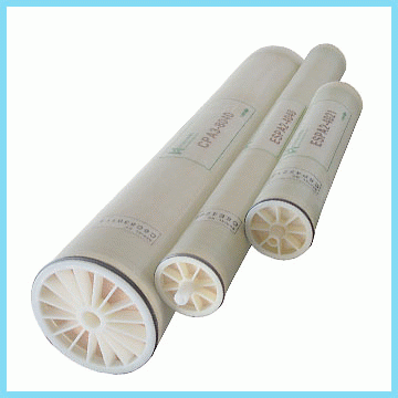
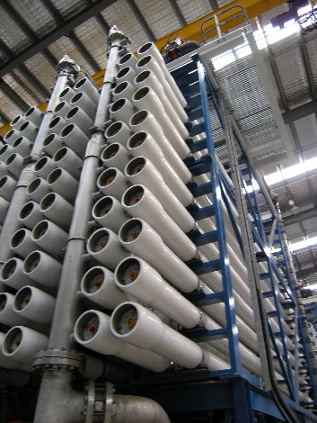
Fig. 4 RO membrane (a) elements and (b) pressure vessels.
|
(a) |
|
|
(b) |
|
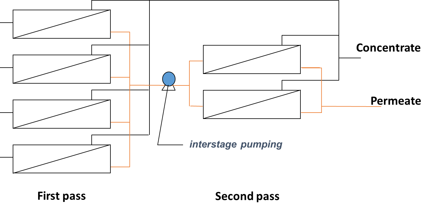
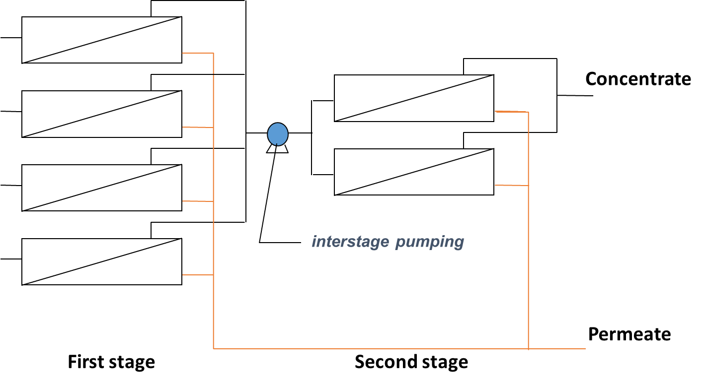
Fig. 5 RO membrane staging through the (a) permeate with two passes to improve water quality or (b) concentrate with two stages to improve water recovery.
Synergetic effects and motivation for the implementation of the technology
- Production of high quality water for reuse applications
Due to their ability to remove most dissolved pollutants from water including salts, bacteria, viruses and micro-pollutants, RO membranes, when combined with other treatment technologies, offer the potential to treat wastewaters and produce very high quality effluent that can then be reused for a range of applications. Indeed, the potential of RO membranes has been demonstrated to produce the high quality waters required for a range of industrial application such cooling systems, electronics production and cleaning processes and production in the pharmaceutical and food and beverage industries as well as for the production of drinking water from different water sources.
Technology requirements and operating conditions
A key advantage of the RO membrane technology is that the elements are modular and standardised (all manufacturers produce elements in the same sizes). Elements exist in sizes of 2, 4, 8 and 16 inches (referring to the diameter of the element) and each type will be able to accommodate different inlet flows. The design of a plant will then have to be defined based on the flow, permeate quality and recovery requirements. RO membranes will typically be operated at fluxes between 15 and 25 L/(m2.h). The operating pressure will depend on the characteristics of the feed water but ranges from 5-10 bar for municipal wastewater applications up to 50-60 bar for seawater desalination.
The main limitation of the technology is fouling, defined as the accumulation of materials (organics, inorganics, particulate and biofilm) on the surface and within the structure of the membrane, which will affect the treatment and operational performance of the system. Most systems have pre-treatment stages to remove solids with for example depth filtration or membranes (ultra or micro filtration) so particulate fouling is often very limited. Similarly, organic fouling can be controlled by removing organic matter before it reaches the RO membranes. Alternatively, inorganic fouling can be limited by direct dosing of acid to reduce the pH (6-7) and/or antiscalants to limit the precipitation in the membranes as the compounds are concentrated. Also, biofouling (biofilm formation) can be controlled with the use of disinfection with chlorine or chloramine. As a strong oxidant, chlorine can damage the RO membrane material so it has to be dosed and then quenched before reaching the membranes. Based on this, in particular for wastewater applications, RO membranes will be the last stage of an extensive treatment train to tackle the remaining dissolved pollutants to produce a high quality effluent for reuse.
Key performance indicators
As stated above, the operation and performance of an RO system will greatly depend on the source water and the application but the performance of the system can be assessed based on number of key parameters in relation to the permeate produced (recovery) and filtration performance (pressure and permeability) as summarised in Tab. 1. The quality of the permeate will evidently be critical but again will depend on the application (industrial, potable …) and the associated regulations. The permeability of solutes decreases (the rejection increases) with an increase in the:
- degree of dissociation: weak acids, for example lactic acid, are rejected much better at higher pH when the dissociation is high
- ionic charge: e.g., divalent ions are better rejected than monovalent ions
- molecular weight: higher molecular weight species are better rejected
- nonpolarity: less polar substances are rejected better
- degree of hydration: highly hydrated species, e.g., chloride, are better rejected than less hydrated ones, e.g.,nitrate
- degree of molecular branching: e.g., iso-propanol is better rejected than n-propanol.
Tab. 1. Key parameters for RO membranes operation (values range depends on membrane supplier)
|
Parameter |
Unit |
|
Operating pressure (inlet pressure) |
bar |
|
Recovery |
% |
|
Permeability |
L/(m2.h.bar) |
|
Pressure drop |
bar |
|
Salt rejection |
% |
Links to related topics and similar reference projects
|
Source |
Application |
Reference |
|
Industrial and municipal wastewater |
Industrial use (cooling towers, boilers) |
|
|
Distillery wastewater |
Onsite cleaning processes |
|
|
Industrial and municipal wastewater |
Industrial use |
Case Studies applying the technology


Publications
- R. Radcliff and A. Zarnadze, Application of Membrane Technology to the Production of Drinking Water, 2004